
Pulseaudio Crossover Rack - Online Help
Contents
Theory of operation
Pulseaudio Crossover Rack offers you a graphical user interface to build arbitrarily
complex multi-way speaker crossovers for stereo systems. The two-channel limitation
(stereo) is hardcoded at the moment. If you have a use case for multi-channel crossovers
please contact me and we will see how to proceed.
The input sink is always named "PaXoverRack.Input" and will be set as default sink
after inserting the filter chain.
This allows any pulseaudio-enabled application to play sound through Pulseaudio
Crossover Rack by system-wide default.
This program makes use of the Pulseaudio audio server backend which is used by many of today's linux and unix desktop environments. It also uses a set of LADSPA plugins, namely ladspa-t5-plugins for the heavy lifting of DSP/audio processing.
The LADSPA plugins are inserted into the pulseaudio system by
load-module ... statements. The complete chain is persisted into your
$HOME/.config/pulse/default.pa file and all the filters are loaded
automatically on each start of the pulseaudio system, which most of the time is
started in the background when you start your favourite desktop environment.
All filter and splitter sinks names are prefixed by "PaXoverRack."
As pulseaudio does not offer any means of changing the parameters of inserted
LADSPA sinks after insertion i chose to equip all my LADSPA plugins with a shared
memory interface which is exposed via the /dev/shm shared memory fs.
This way Pulseaudio Crossover Rack can change all filter parameters in real time
and the results can be heard immediately. As Low-/High-pass filters can have
their cutoff frequency parameter linked together (See
parameter linking) you can even modify the crossover
frequency between f.ex. a midrange and a tweeter on the fly by simply draging a
slider and immediately hear the results. Neat, huh? :)
Attention!
After changing the filter chain you need to reinsert modules by pressing the
stop ( ) and then the play button (
 )
or by accessing the "Pulseaudio > Insert Modules" menu entry.
Changes to the filter chain will not be and cannot be reflected in real time.
)
or by accessing the "Pulseaudio > Insert Modules" menu entry.
Changes to the filter chain will not be and cannot be reflected in real time.
Prerequisites
For Pulseaudio Crossover Rack to work you need a multi channel soundcard with
a stereo pair of outputs for each speaker pair you want to drive, so for a
3-way stereo setup you need a six channel soundcard. It doesn't matter if the
channels are named after the surround theme, for example you could use the
center/LFE channel to drive your tweeters.
Please make sure in the pulseaudio settings that the sound card is set to
multichannel mode as shown below:

Configuring sample rate and depth of the pulseaudio daemon
I also recommend to make the following four changes to your/etc/pulse/daemon.conf:
default-sample-format = float32le
default-sample-rate = 192000
avoid-resampling = false
resample-method = speex-float-10 # or if supported use the better resampler "soxr-vhq"
Especially when using the subsample delay, use the highest sample rate you can get away with performance-wise (I used 192kHz in the example above). Also use the highest quality resampler that performance allows. (sox-hq and libsamplerate support are not yet compiled into pulseaudio in ubuntu 18.04 releases, they are from 18.10 on...)
Realtime scheduling for the pulseaudio daemon
If you want to run the pulseaudio daemon with realtime scheduling which will maybe help if you experience stuttering or desynchronization of outputs, please make the following changes:
Add this to your/etc/security/limits.conf, replace <username> with the actual username you run pulseaudio with:<username> - rtprio 95/etc/pulse/daemon.conf:realtime-scheduling = yes
realtime-priority = 5You have to logout of your session and login again for this to take effect. When in doubt restart your machine after these changes.
Known problems
Pulseaudio in version <= 13.99.2 has a bug that prevents switching the default sink. This keeps Pulseaudio Crossover Rack from working correctly. Affected distors include Linux Mint 20, Ubuntu 20.x and possibly others that were insane enough to ship a prerelease version of a system daemon. A fix for debian/ubuntu based systems can be found here: https://gitlab.com/t-5/pulseaudio_13.99_sink_fixes
Available filters
- Slope: 24dB/octave
- 6dB attenuation at the cutoff frequency
- Slope: 24dB/octave
- 6dB attenuation at the cutoff frequency
- Slope: 12dB/octave
- 6dB attenuation at the cutoff frequency
- Slope: 12dB/octave
- 6dB attenuation at the cutoff frequency
- Slope: 6dB/octave
- 3dB attenuation at the cutoff frequency
- Slope: 6dB/octave
- 3dB attenuation at the cutoff frequency
- Slope: 12dB/octave
- 3dB attenuation at the cutoff frequency
- Slope: 12dB/octave
- 3dB attenuation at the cutoff frequency
- Slope: 12dB/octave
- 3dB attenuation at the cutoff frequency
- Slope: 12dB/octave
- 3dB attenuation at the cutoff frequency
- Slope: 18dB/octave
- 3dB attenuation at the cutoff frequency
- Slope: 18dB/octave
- 3dB attenuation at the cutoff frequency
- Low shelving EQ with adjustable frequency, gain and Q
- 3 peaking EQs with adjustable frequency, gain and Q
- High shelving EQ with adjustable frequency, gain and Q
- Delay freely adjustable from 0 to 1000ms.
- Actual delay is rounded to the nearest whole sample and thus depends
on the sampling rate of the pulseaudio server.
Example 1ms delay @44.1kHz SR: actual delay is: round(0.001s * 44100/s) / (44100/s) = 0.997732ms - Completely linear frequency and phase response.
- Delay freely adjustable from 0 to 1000ms.
- Combines a sample accurate delay with a fractional delay filter to achieve sub-sample accuracy.
- Depending on the fractional delay the frequency response has a low-pass characteristic. If the fractional delay is 0, phase and frequency response are linear, if the fractional delay is 0.5 samples the frequency response drops to 0 at nyquist frequency (1/2 sampling rate).
- This filter should not be used on tweeters when sampling rate is less than 96 kHz! 192kHz SR is probably most desireable in this case.
User interface
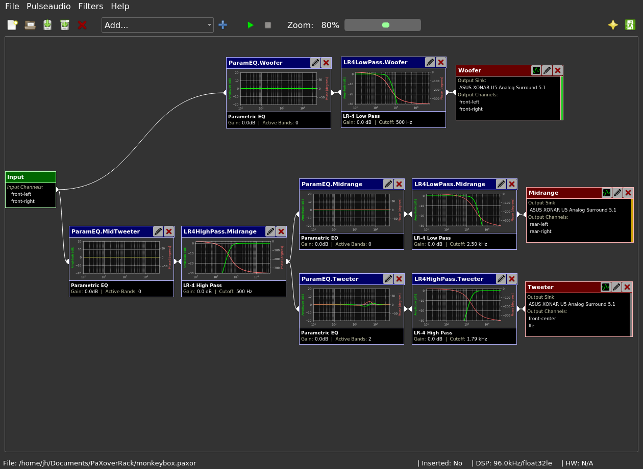
Here is the main window of the program showing a very basic two way crossover:

Toolbar
Here are the icons on the toolbar and their functions:

|
Creates a new, empty crossover file with just an input. |

|
Opens an existing crossover file (file extension: .paxor). |

|
Saves the currently opened file. |

|
Saves the currently opened file with a different name. |

|
Closes the currently opened file. |

|
Dropdown selection to choose a filter our output to be inserted. |

|
Press this button to actually insert the chosen filter/output. |
|
|
Insert the filters in the currently loaded file into the pulseaudio system. |
|
|
Remove all crossover filters from the pulseaudio system regardless of the file currently loaded. |

|
Use this slider to change the zoom level of the filters/outputs. |

|
Show the information dialog about Pulseaudio Crossover Rack. |

|
Exit Pulseaudio Crossover Rack. |
Menu
The menu is essentially structured very similarly to the toolbar. There are only three menu items that provide additional functionality and these are described here:
-
Pulseaudio
-
Delete default.pa (Reset to system defaults)
This function will remove your$HOME/.config/pulse/default.pafile so pulseaudio will use the system defaults in/etc/pulse/default.paagain after a restart of the pulseaudio server.
Use this function in case pulseaudio will not start up because of some garbage in the file. -
Restart pulseaudio
Forcibly restarts the pulseaudio server by calling it's shutdown functionality and killing it with signal KILL after three seconds. After the pulseaudio server is stopped it will be restarted again.
Only use as a last resort, this should normally not be necessary!
-
Delete default.pa (Reset to system defaults)
-
Filters
- Show Global FRD Dialog / Show FRD Dialog for...
These menu entries show the dialog windows for working with FRD (frequency response) files.
Please look at it's own section in the online help which be found here: Working with FRD files (speaker response curves)
- Show Global FRD Dialog / Show FRD Dialog for...
Input widget

The input widget is always contained in a .paxor file an represents the input sink of the filter chain. From it's output connection ponit you can draw connections to other filters or outputs.
Filter widgets

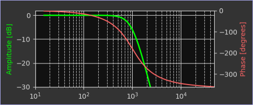
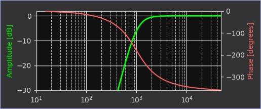
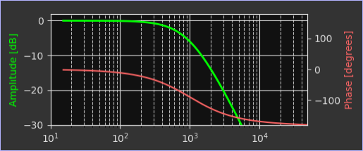
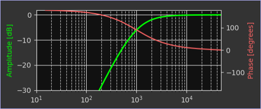
- The filter widget shows the chosen filter/sink-name in the top left corner.
- On the top right corner are buttons for editing a filter and for deleting a filter.
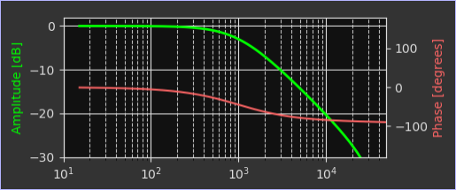
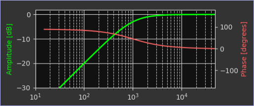
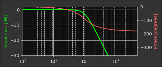
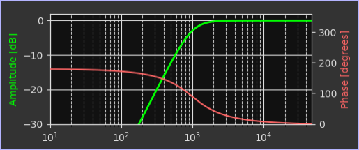
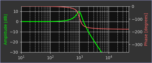
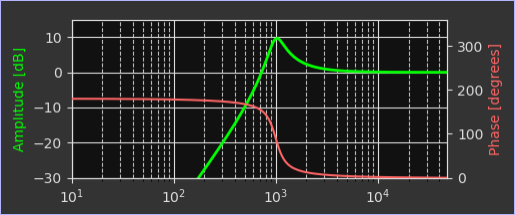
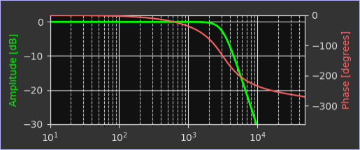
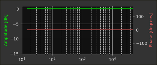
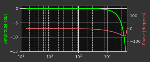
- The area below the caption shows the frequency and phase response of the filter.
- The bottom area shows infos about the current state of the filter.
Output widgets

- The output widget shows the chosen output/sink-name in the top left corner.
-
On the top right corner are three buttons:
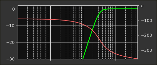
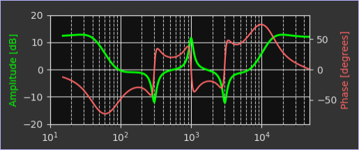
- The first button shows the overall frequency response of the filter chain from input to output.
- The second button opens the dialog to choose the output sink (soundcard) and the channels of the output sink.
- The third button deletes the output.
- The area below the caption shows the currently chosen output sink and output channels.
Connections
- Connections between input/filters/outputs are draw as white bezier curves.
- A input/filter/output with an established connection has its connection points drawn in full white instead of an empty white semicircle in case of no incoming or outgoing connections.
- New connections can be made by using the mouse to drag from one connection point to another connection point.
- Established connections can be deleted by right clicking a connection point (doesn't matter if on the input or output side) and choosing "Disconnect..."
Inserting and removing filter modules into/from pulseaudio

The GUI shows a green "Play" button and a red "Stop" button. The "Play"
button will insert the filter modules into the pulseaudio system, the "Stop" button will
remove them. When inserting modules all modules already inserted by Pulseaudio Crossover Rack
will be removed first. On startup or when loading a file from disk the program will check, if
there is a config snippet in $HOME/.config/pulse/default.conf with a UUID which
matches the currently loaded file. If the UUIDs in the file and the config snippets match, the
program will assume that modules are already loaded and will try to enable real time
parametrization of the filter modules.

Before removing the modules a dialog window will pop up where you can choose the new default sink (as shown above).
After a successful removal or insertion of modules all running streams are reconnected to the new default sink. Of course in case of module insertion the input of the crossover filter chain is set as new default sink.
Loading and unloading actions and results will be shown in the Console Dialog.
The Console Dialog

When you try to unload or insert modules all actions and their results are shown in the console dialog window.
If you check the checkbox next to "Automatically close after..." you can adjust the number of seconds after which the dialog window will close itself automatically.
Filter editing

If you click the edit button on a filter (the on with the little pencil icon) you will be presented with a dialog like shown above with sliders and textedit boxes for all the filter's parameters (depends on the type of filter). For exact value entry use the textedit field, for quick and coarse adjustments use the sliders. Filter parameters are updated immediately and if the crossover file is already active in pulseaudio all parameters are updated in real time, so you can hear the results immediately.
Linking of low-/highpass frequency parameters

This dialog can be opened by pressing the "Edit links" button in the filter
edit dialog. It allows you to link two frequency parameters of high- and lowpass filters
and of Linkwitz Transform filters (target frequency).
As a result, if you change the frequency of one filter the other one is apdated, too.
This is abviously useful if you want to change the crossover frequency between for
example the woofer and the midrange and check which cutoff frequency suits you best.
You can add a link to another filter by clicking the blue + icon. An existing link
can be removed by clicking the red x icon.
You can link more than two filters together, which might be useful if you have several
chained HP/LP/LT filters in one signal branch and those should all change their frequency
at once.
Working with FRD files (speaker response curves)
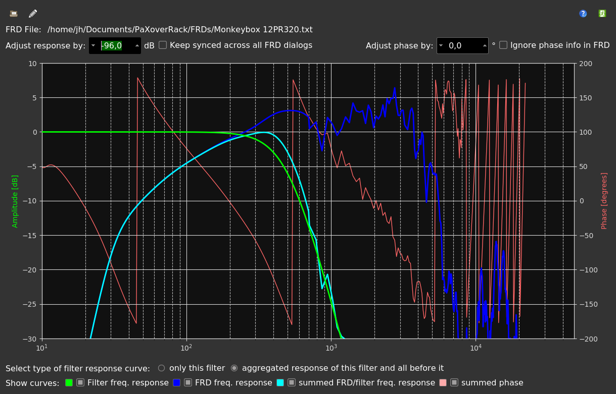

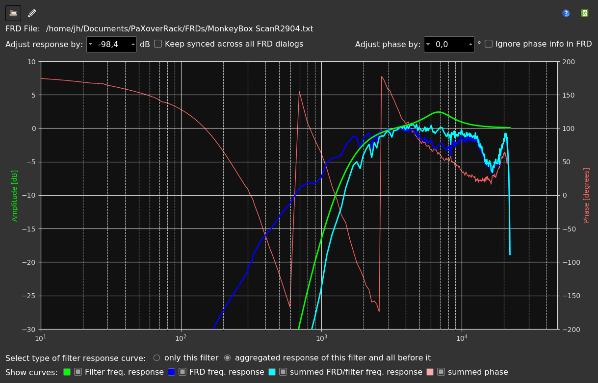

In the "Filters" menu you can show a FRD dialog for any of the filters in your crossover file. This dialog lets you load a FRD file from disk which contains a frequency/phase response measurement for a single speaker driver. You can choose if you want to see the speaker response summed with only the local filter response of the chosen filter or the cascaded filter response of the chosen filter and all filters inserted before it in the filter chain up to the input.
You can also show a "Global FRD dialog" which can show the summed up response curves for all open FRD dialog windows. When using this dialog it is recommended to open a FRD dialog for each filter directly before an output.
Time alignment measurements
In the "Measurements" menu yout will find the menu entry "Time alignment measurements...". This will open the dialog to conduct time alignment measurements using wavelets. It can also be opened by pressing F9.

Theory of operation:
To align the delay of two drivers at the crossover frequency you have to follow these steps:
-
Setup your hardware:
- Connect a loopback cable from an output that receives the unaltered, unfiltered signal. Connect this loopback cable to one of your soundcard inputs, I always choose the right channel for that.
- Connect the measurement microphone/preamp to another soundcard input, I always use the left channel for that.
- Choose input channels accordingly in the lower left corner of the dialog.
-
Setup the wavelet:
- Choose wavelet frequency - use the exact crossover frequency here
- Choose wavelet duration - I recommend something like 6 periods and use a Blackman window which will result in a frequency spread of the wavelet of 1/3 of an octave.
- Choose either "Peak in the center" or "Zero crossing int the center". This will determine where you have to set markers after measuring.
- Choose appropriate gain (output volume of the wavelet). Maybe see next step for that.
-
Level check:
The Icon will bring up the level check dialog where you
can play different types of noise for a certain duration. While playing noise the input levels
will be monitored and peak levels will be shown after playing the noise. This can help you
setup playback volume and soundcard input gains.
Icon will bring up the level check dialog where you
can play different types of noise for a certain duration. While playing noise the input levels
will be monitored and peak levels will be shown after playing the noise. This can help you
setup playback volume and soundcard input gains.
-
Actual measurement:
- Set wavelet frequency to the crossover frequency of the two drivers that you want to time align.
- Play wavelet to first speaker driver (mute all the other speakers by disconnecting them or switching off amps). The measurement will be shown as green line.
- Play wavelet to second speaker driver. The old measurement of the first dirver will be shown in cyan and the new measurement will be shown in green.
- Adjust zoom levels and scroll so you can clearly see the wavelets.
- Depending on what wavelet type you chose set markers by pressing or dragging left/right mouse buttons in the oscilloscope screen to either the center zero crossing or the center peak of the wavelet. After setting both markers the delay between the two markers will be shown on the bottom (in milliseconds and meters). Depeding on which driver you measured first you will either have to adjust the delay of the first or the second driver, whichever plays first timewise (wavelet is more to the left of the oscilloscope screen).
- After adjusting the delays repeat the measurement and see how well the alignment fits now.